Laser Direct Writing via Two Photon Polymerization (LDW via TPP), also known as 3D Lithography (3DL), is a method of obtaining structures with sub-micrometric features (lateral features down to 90 nm) using LDW. The key element is the two-photon absorption and the transverse Gaussian intensity profile of the incident laser beam. Irradiation of the used photoresist initiates a chemical reaction that results in polymeric chains that result in solid microstructures. Generally, a photoresist appropriate for 3DL is comprised of 3 main components: monomer, photoinitiator and solvent. During the irradiation process, the photoinitiator molecules are ionized, resulting in free radicals (molecules with active terminations). These ionized molecules react with monomer molecules and initiate a chain polymerization process.
The photoresist is liquid acrylic, optimized for LDW via TPP, where processing is done with the microscope objective immersed in the photoresist. The laser source is a Er: doped fiber laser system that delivers 120 fs pulses, with a repetition rate of 80 MHz, centered on a wavelength λ = 780 nm (through means of a Periodically Poled Lithium Niobate – PPLN frequency doubler at the output end of the fiber). Processing is done with average laser powers between 10-15 mW. Laser pulses are delivered to the sample through an inverted Zeiss microscope, terminated with a 100x NA 1.3 microscope objective.
In order to design and obtain an optical enhancement of a PMP-optical fiber coupled system multiple diffraction gratings have been designed and fabricated on mechanically processed optical fiber, through means of Two-Photon Polymerization via laser direct writing (3D Lithography – 3DL).
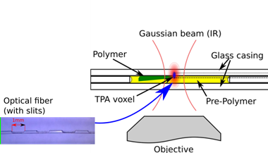
In order to write the diffraction grating, the mechanically processed optical fiber was submersed in the appropriate photoresist (IP-L 780). The sample setup was based on a sandwich-like casing in order to position and fix the optical fiber, while maintaining an immersion-free laser processing (see Figure 1).

Figure 1 – Sandwich-like sample setup for writing diffraction gratings on the surface of a mechanically processed optical fiber via 3DL.
This setup allowed for the intended laser processing to take place, but it has shown one main disadvantage: fiber rotation. The fiber itself is round, yet the slits on which we needed to write the diffractive structures are flat. Since 3DL is a high resolution optical technology, it means it is highly sensitive to the substrate surface roughness, planarity and tilt.
Surface roughness did not show any noticeable interference with neither the fabrication process, nor the structural integrity of the gratings (more precisely: surface adhesion).
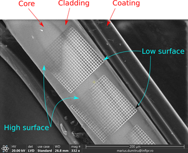
Sample planarity, however, is shown to negatively impact the resulting structures, even though it does not impact the fabrication process. The optical fiber is mechanically process not only to remove the coating and cladding, but to expose the core itself. However, the resolution needs to be higher in order for the slits to have appropriate planarity. It seems the height of the core surface varies above 5 um, as indicated by Figure 2. The laser focal point moves inside the substrate (fiber core) due to the substrate variations in planarity. The tilt was determined with 3 points in this case (corners of the grating).

Figure 2 – Electron micrograph image showing the issues imposed on the fabrication process by the planarity of the slit in the optical fiber.
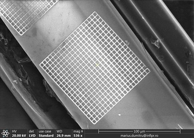
Optimal structures (see Figure 3) were obtained through variation of the tilt, power, writing speed, structure height. These structure were obtained for a writing speed of 80 μm/s, an average laser power of 28.8 mW. The size of the grating is 100 x 100 x 2.5 μm. The grating has a step of 5 μm (2 μm polymer, 3 μm space).

Figure 3 – Optimal diffraction grating fabricated via 3DL on the surface of mechanically produced slits in an optical fiber.


